how to draw a tree in adobe animate
About drawing
The drawing tools in Adobe Animate let you create and modify lines and shapes for the artwork in your documents. The lines and shapes you create in Animate are all lightweight vector graphics, which help keep your FLA file size small.
Before you draw and paint in Animate, it is important to understand how Animate creates artwork, and how drawing, painting, and modifying shapes can affect other shapes on the same layer.
Vector and bitmap graphics
Computers display graphics in either vector or bitmap format. Understanding the difference between the two formats helps you work more efficiently. Using Animate, you can create and animate compact vector graphics. Animate also imports and manipulates vector and bitmap graphics that were created in other applications.
Vector graphics describe images by using lines and curves, called vectors, that also include color and position properties. For example, the image of a leaf is described by points through which lines pass, creating the leaf's outline. The color of the leaf is determined by the color of the outline and the color of the area enclosed by the outline.
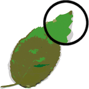
When you edit a vector graphic, you modify the properties of the lines and curves that describe its shape. Move, resize, reshape, and change the color of a vector graphic without changing the quality of its appearance. Vector graphics are resolution independent; that is, they can be displayed on output devices of varying resolutions without losing any quality.
Bitmap graphics describe images using colored dots, called pixels, arranged in a grid. For example, the image of a leaf is described by the specific location and color value of each pixel in the grid, creating an image in much the same manner as a mosaic.
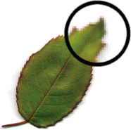
When you edit a bitmap graphic, you modify pixels rather than lines and curves. Bitmap graphics are resolution dependent, because the data describing the image is fixed to a grid of a particular size. Editing a bitmap graphic can change the quality of its appearance. In particular, resizing a bitmap graphic can make the edges of the image ragged as pixels are redistributed within the grid. Displaying a bitmap graphic on an output device that has a lower resolution than the image itself also degrades its quality.
Paths
Whenever you draw a line or shape in Animate, you create a line called a path. A path is made up of one or more straight or curved segments. The beginning and end of each segment is denoted by anchor points, which work like pins holding a wire in place. A path can be closed (for example, a circle), or open, with distinct endpoints (for example, a wavy line).
You change the shape of a path by dragging its anchor points, the direction points at the end of direction lines that appear at anchor points, or the path segment itself.
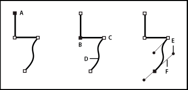
A. Selected (solid) endpointB. Selected anchor pointC. Unselected anchor pointD. Curved path segmentE. Direction pointF. Direction line.
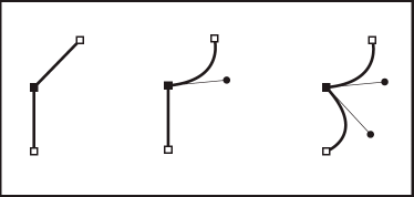
Paths can have two kinds of anchor points: corner points and smooth points. At a corner point, a path abruptly changes direction. At a smooth point, path segments are connected as a continuous curve. You can draw a path using any combination of corner and smooth points. If you draw the wrong type of point, you can always change it.
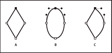
A. Four corner pointsB. Four smooth pointsC. Combination of corner and smooth points.
A corner point can connect any two straight or curved segments, while a smooth point always connects two curved segments.
![]() Don't confuse corner and smooth points with straight and curved segments.
Don't confuse corner and smooth points with straight and curved segments.
A path outline is called a stroke. A color or gradient applied to an open or closed path interior area is called a fill. A stroke can have weight (thickness), color, and a dash pattern. After you create a path or shape, you can change the characteristics of its stroke and fill.
Direction lines and direction points
When you select an anchor point that connects curved segments (or select the segment itself), the anchor points of the connecting segments display direction handles, which consist of direction lines that end in direction points. The angle and length of the direction lines determine the shape and size of the curved segments. Moving the direction points reshapes the curves. Direction lines don't appear in the final output.
A smooth point always has two direction lines, which move together as a single, straight unit. When you move a direction line on a smooth point, the curved segments on both sides of the point are adjusted simultaneously, maintaining a continuous curve at that anchor point.
In comparison, a corner point can have two, one, or no direction lines, depending on whether it joins two, one, or no curved segments, respectively. Corner point direction lines maintain the corner by using different angles. When you move a direction line on a corner point, only the curve on the same side of the point as that direction line is adjusted.
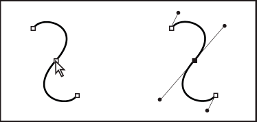
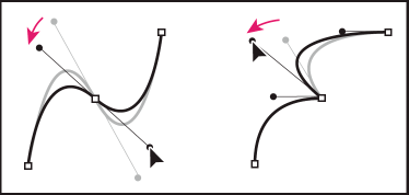
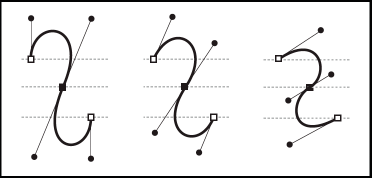
Direction lines are always tangent to (perpendicular to the radius of) the curve at the anchor points. The angle of each direction line determines the slope of the curve, and the length of each direction line determines the height, or depth, of the curve.
Drawing modes and graphic objects
In Animate, you can create several different kinds of graphic objects by using different drawing modes and drawing tools. Each kind has its own advantages and disadvantages. By understanding the capabilities of the different graphic object types, you can make good decisions about which types of objects to use in your work.
![]() In Animate, graphic objects are items on the Stage. Animate lets you move, copy, delete, transform, stack, align, and group graphic objects. "Graphic objects" in Animate are different from "ActionScript objects," which are part of the ActionScript® programming language. Do not confuse the two uses of the term"objects." For more information on objects in the programming language, see About Data Types in Learning ActionScript 2.0 in Adobe Animate, or Data types inthe ActionScript 3.0 Developer's Guide.
In Animate, graphic objects are items on the Stage. Animate lets you move, copy, delete, transform, stack, align, and group graphic objects. "Graphic objects" in Animate are different from "ActionScript objects," which are part of the ActionScript® programming language. Do not confuse the two uses of the term"objects." For more information on objects in the programming language, see About Data Types in Learning ActionScript 2.0 in Adobe Animate, or Data types inthe ActionScript 3.0 Developer's Guide.
Merge Drawing mode
The default drawing mode automatically merges shapes that you draw when you overlap them. When you draw shapes that overlap each other in the same layer, the top-most shape cuts away the part of the shape underneath it that it overlaps. In this way, drawing shapes is a destructive drawing mode. For example, if you draw a circle and overlay a smaller circle on top of it, and then select the smaller circle and move it, the portion of the second circle that overlaid the first circle is removed.
When a shape has both a stroke and a fill, they are considered separate graphic elements that can be selected and moved independently.
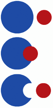
Enter Merge Drawing mode
-
Select the Merge Drawing option in the Tools panel.
-
Select a drawing tool from the Tools panel and draw on the Stage
![]() By default, Animate uses the Merge Drawing mode.
By default, Animate uses the Merge Drawing mode.
Object Drawing mode
Creates shapes referred to as drawing objects. Drawing objects are separate graphic objects that do not automatically merge together when overlaid. This lets you overlap shapes without altering their appearance if you move them apart, or rearrange their appearance. Animate creates each shape as a separate object that you can individually manipulate.
When a drawing tool is in Object Drawing mode, the shapes you create with it are self-contained. The stroke and fill of a shape are not separate elements, and shapes that overlap do not alter one another. When you select a shape created using Object Drawing mode, Animate surrounds the shape with a rectangular bounding box to identify it.
![]() Set preferences for contact sensitivity when selecting shapes created using the Object Drawing mode.
Set preferences for contact sensitivity when selecting shapes created using the Object Drawing mode.
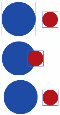
Enter Object Drawing mode
To draw shapes using Object Drawing mode, you must explicitly enable it.
-
Select a drawing tool that supports Object Drawing mode (the Pencil, Line, Pen, Brush, Oval, Rectangle, and Polygon tools).
-
Select the Object Drawing button
 from the Options category of the Tools panel, or press the J key to toggle between the Merge and Object Drawing modes. The Object Drawing button toggles between the Merge and Object Drawing modes. You can set preferences for contact sensitivity when you select shapes created with Object Drawing mode.
Convert a Merge Drawing mode created shape to an Object Drawing mode shape
-
Select the shape on the Stage.
-
To convert the shape into an Object Drawing mode shape, select Modify > Combine Objects > Union. After conversion, the shape is treated like a vector-based drawing object that does not alter its appearance by interacting with other shapes.
![]() To join two or more shapes into a single, object-based shape, use the Union command.
To join two or more shapes into a single, object-based shape, use the Union command.
Primitive objects
Primitive objects are shapes that let you adjust their characteristics in the Property inspector. You can precisely control the size, corner radius, and other properties of the shape at any time after you have created it without having to draw it from scratch.
Two types of primitives are available, rectangles and ovals.
-
Select the Rectangle Primitive Tool
 or Oval Primitive Tool
 from the Tools panel.
Overlapping shapes
When you draw a line across another line or painted shape in Merge Drawing mode, the overlapping lines are divided into segments at the intersection points. To select, move, and reshape each segment individually, use the Selection tool.

When you paint on top of shapes and lines, the portion underneath is replaced by whatever is on top. Paint of the same color merges together. Paint of different colors remains distinct. To create masks, cutouts, and other negative images, use these features. For example, the following cutout is made by moving the ungrouped kite image onto the green shape, deselecting the kite, and then moving the filled portions of the kite away from the green shape.
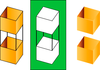
To avoid inadvertently altering shapes and lines by overlapping them, group the shapes or use layers to separate them.
Source: https://helpx.adobe.com/animate/using/drawing.html
0 Response to "how to draw a tree in adobe animate"
Post a Comment